
How to Make Holes for Cabinet Hinges: A Step-by-Step Precision Drilling Guide
- By:
- Date:2026/11/05
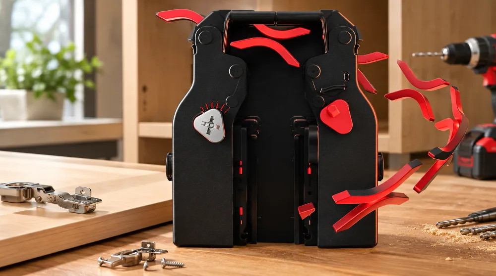
Learning how to make holes for cabinet hinges is an essential skill that transforms raw wood slabs into functional cabinetry. Whether you are building custom kitchen storage from scratch or replacing outdated face hardware with sleek European concealed fittings, drilling the hinge recess requires exacting geometry. Depending on the hinge and cabinet geometry, even a small placement error can cause binding, uneven reveals, or poor alignment.
Mastering how to make holes for cabinet hinges demands the right cutting tools, repeatable reference marks, and a thorough understanding of cup geometry. Once you grasp the relationship between door thickness, boring distance, and hinge cup depth, boring clean, flat-bottomed recesses becomes straightforward.
Understanding Concealed Cabinet Hinges Before Drilling
The Anatomy of a European Cup Hinge
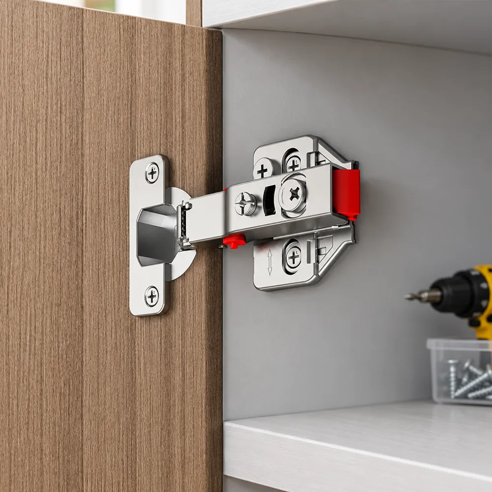
Concealed European hinges rely on a three-part mechanical system: the recessed cup that drops into the door panel, the articulated hinge arm containing internal springs or dampers, and the mounting plate secured to the cabinet carcass wall. The cup housing anchors the mechanical pivot directly inside the core of the door leaf, distributing dynamic weight loads across a wide circular footprint.
Because the structural weight of the swinging panel concentrates within the recessed cup, the mortise cavity must have clean vertical walls and a perfectly flat base. If the cup tilts slightly inside an uneven recess, the entire hinge arm binds during transit, causing premature wear on the pivot pins.
Matching Door Configuration: Full Overlay, Half Overlay, and Inset
Before chucking a bit into your drill, confirm your cabinet door layout. Full overlay configurations position the closed door entirely over the front edge of the cabinet side panel, leaving a tiny perimeter reveal. Half overlay setups allow two adjacent doors to share a single central vertical partition, common in long wardrobe runs.
Inset doors sit entirely flush inside the cabinet face frame or carcass opening, requiring consistent margins on all four sides. Each layout relies on hinges with distinct arm crank angles and mounting plate heights. While the drilling process follows similar mechanical steps, overlay targets directly influence how close to the panel edge you must bore the cup hole.
Deciphering Critical Drilling Terminology
Precision cabinetmaking uses standardized spatial terms that dictate your tool setup. Memorizing these three parameters prevents costly door panel replacements:
- Cup Diameter: The outer dimension of the recessed circular housing, most commonly 35 mm for standard residential furniture, though compact systems may require 26 mm cups.
- Boring Distance (Edge Distance or K-Value): The narrow strip of solid wood remaining between the outer edge of the door and the nearest rim of the bored 35 mm hole. Many concealed hinges use an edge distance around 3 mm to 7 mm, while some models allow a wider range such as 3 mm to 9 mm. Use the drilling diagram for the exact hinge.
- Cup Depth: The vertical distance the bit must plunge into the door panel. Common concealed-hinge cup depths are around 11 mm to 12 mm, but the exact depth must come from the hinge manufacturer’s drilling diagram.
Miscalculating the boring distance changes the door’s position and clearance relative to the cabinet, which can cause binding or an incorrect overlay. Boring too close to the edge creates an unsupported, fragile wood lip prone to chipping.
Essential Tools and Workshop Setup
Forstner Bit vs. Standard Wood Bits
Standard twist and spade bits are generally unsuitable because they do not produce the required flat-bottomed, accurately sized recess and may increase wandering, tear-out, or veneer damage. Twist bits lack the geometry for a clean cylindrical pocket, while spade bits can vibrate and tear delicate surface layers.
Only a dedicated 35 mm Forstner bit or specialized multi-spur machine bit can cut this recess safely. Forstner bits guide themselves with an outer rim that shears wood fibers before the interior lifting knives clear the waste, leaving a flat-bottomed cylindrical pocket with clean shoulders.
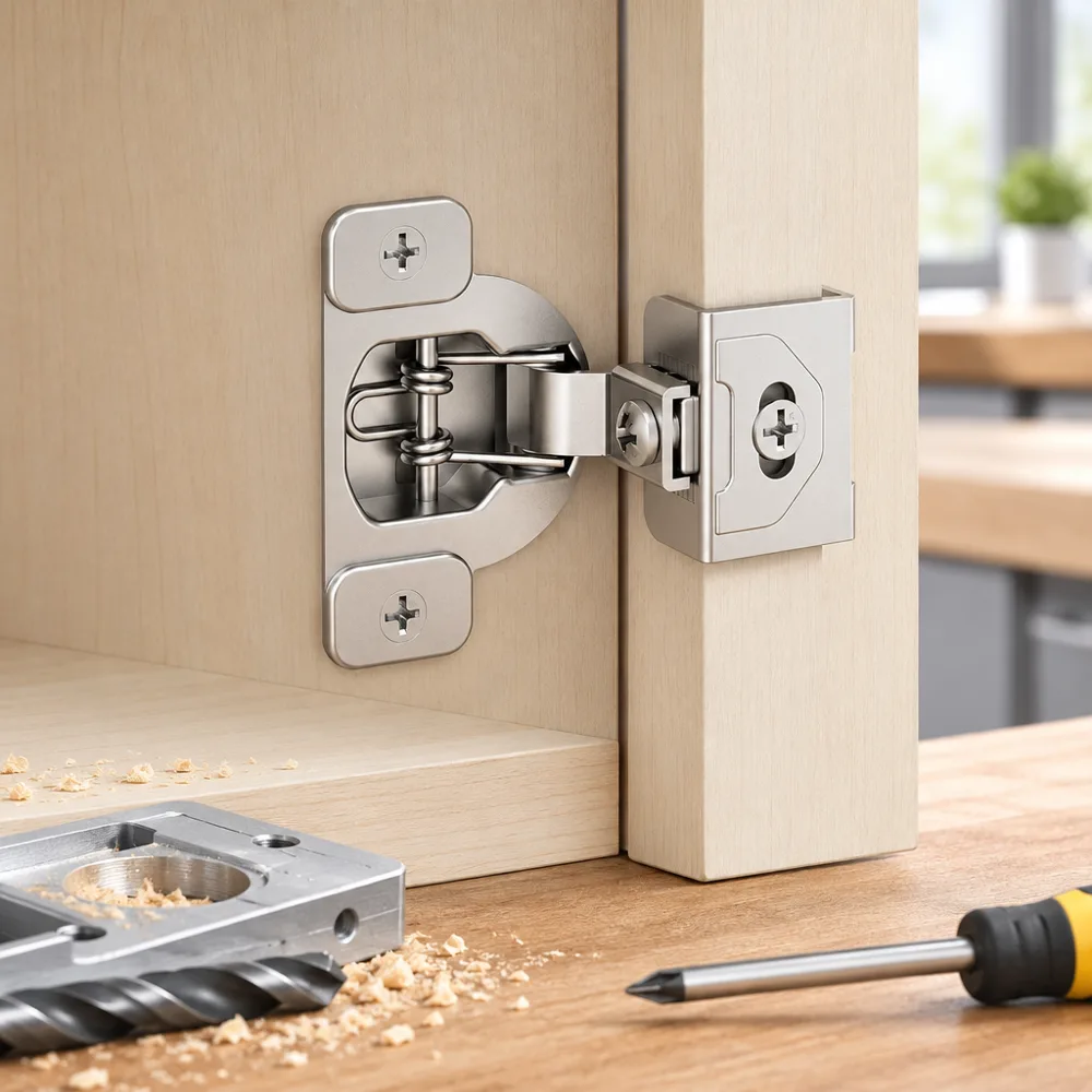
Drilling Setup: Hand Drill, Alignment Jig, or Drill Press
Selecting your drilling platform depends on project volume and workshop machinery. While a handheld drill can bore suitable recesses when paired with a reliable jig, dedicated shop tools provide better consistency across multiple doors.
| Tool Platform | Setup Complexity | Perpendicular Accuracy | Ideal Application |
|---|---|---|---|
| Hand Drill (Freehand) | Low | Moderate to Poor | Emergency field replacements only |
| Hand Drill with Commercial Jig | Moderate | High | On-site cabinetry installation and small workshops |
| Benchtop Drill Press | High (initial fence setup) | Very high | Production runs, solid timber stiles, and custom kitchens |
For most home woodworkers, an entry-level polycarbonate drill guide with integrated metal bushings offers an excellent balance. These jigs register against the panel corner, lock in your desired edge setback, and stop the drill bit at a preset mechanical depth.
Workshop Safety and Panel Protection
Drilling large-diameter recesses produces dense, fine wood shavings, especially in high-density fiberboard and melamine-faced particleboard. Always secure your workpiece firmly to your workbench using protective clamp pads to prevent marring finished surfaces.
Placing a sacrificial piece of scrap hardwood underneath the clamped door provides a rigid backer. If your Forstner bit’s center spur approaches the door face, firm backing support prevents veneer blisters or outward panel deflection under vertical plunge pressure.
Measuring and Layout Calculation for Cabinet Doors
Determining Vertical Hinge Placement
Industry convention places the top and bottom hinge centers roughly 75 mm to 100 mm from the respective ends of the door leaf. On very tall pantry units or heavy solid oak doors, a third or fourth hinge is positioned between them to distribute dead load evenly.
Before marking these vertical positions, inspect the interior layout of the cabinet carcass. Ensure your intended hinge locations do not collide with fixed interior shelf pins, pull-out wire baskets, or integrated drawer runners. Shifting a hinge center by 20 mm vertically to bypass an interior shelf is far easier than modifying shelf hardware later.
Calculating Cup Centerline and Edge Distance
Drill press fences and hand jigs align on the center point of the 35 mm circle rather than its perimeter. Calculating this center reference requires basic arithmetic combining the manufacturer’s specified edge distance with the radius of the bit.
For example, because a 35 mm bit has a radius of 17.5 mm, adding a 5 mm edge distance yields a centerline setback of 22.5 mm from the door edge. Scribe this layout line along the door stile using a calibrated combination square, taking care to measure from the true reference edge of the door.
Always double-check the technical diagram for your selected hinge model before scribing. If that model specifies a 3 mm edge distance, your center mark moves to 20.5 mm from the edge, while some models supporting wider margins may place the center at 26.5 mm.
Transferring Marks to Door and Cabinet Box
Lay your prepared cabinet door flat beside the carcass frame to confirm orientation. Mark the top and bottom orientations clearly with painter’s tape to avoid boring holes on the wrong edge of a handed panel.
Use a sharp mechanical pencil or a fine layout knife to strike the intersecting vertical and horizontal crosshairs. A sharp marking knife severs surface grain fibers, giving the Forstner bit’s centering spur an immediate physical detent to bite into without wandering across the wood.
Step-by-Step Guide: How to Drill 35 mm Cabinet Hinge Holes
Step 1: Marking the Center Point and Establishing the Indent
Begin by stabilizing the door on your workbench face-down. Position an automatic spring-loaded center punch or an awl directly onto the intersection of your measured crosshairs and press down until a crisp dimple forms in the core material.
This small dimple serves as an anchor. When you lower the rotating Forstner bit, its pointed brad center locates into this depression immediately, preventing the tool from skittering across slippery melamine or finished hardwood stiles.
Step 2: Calibrating Drilling Depth
Common 35 mm cup recesses are around 11 mm to 12 mm deep, though your hinge’s drilling diagram sets the exact figure. Because standard cabinet doors are commonly 18 mm to 19 mm thick, you only have about 6 mm to 8 mm of material left before boring completely through the decorative front face.
Fasten a steel mechanical stop collar onto the shank of your Forstner bit, locking its set screw firmly against a flat ground section of the shaft. Alternatively, lower your drill press quill and lock the brass mechanical depth stop nut to restrict vertical plunge to the exact millimeter.
Step 3: Drilling the Cup Recess
Use the bit manufacturer’s recommended speed for a 35 mm Forstner bit and your panel material. Start conservatively, and reduce speed if the bit overheats, burns the surface, or struggles to clear chips. Excessive speed creates friction that scorches the timber and dulls the cutting edges.
Plunge the bit smoothly into the panel using a light pecking motion. Advance roughly 3 mm, lift the bit slightly while spinning to evacuate wood chips, and plunge again until the stop collar contacts the panel surface. Never force the cut; let the sharp edges slice the wood fibers naturally.
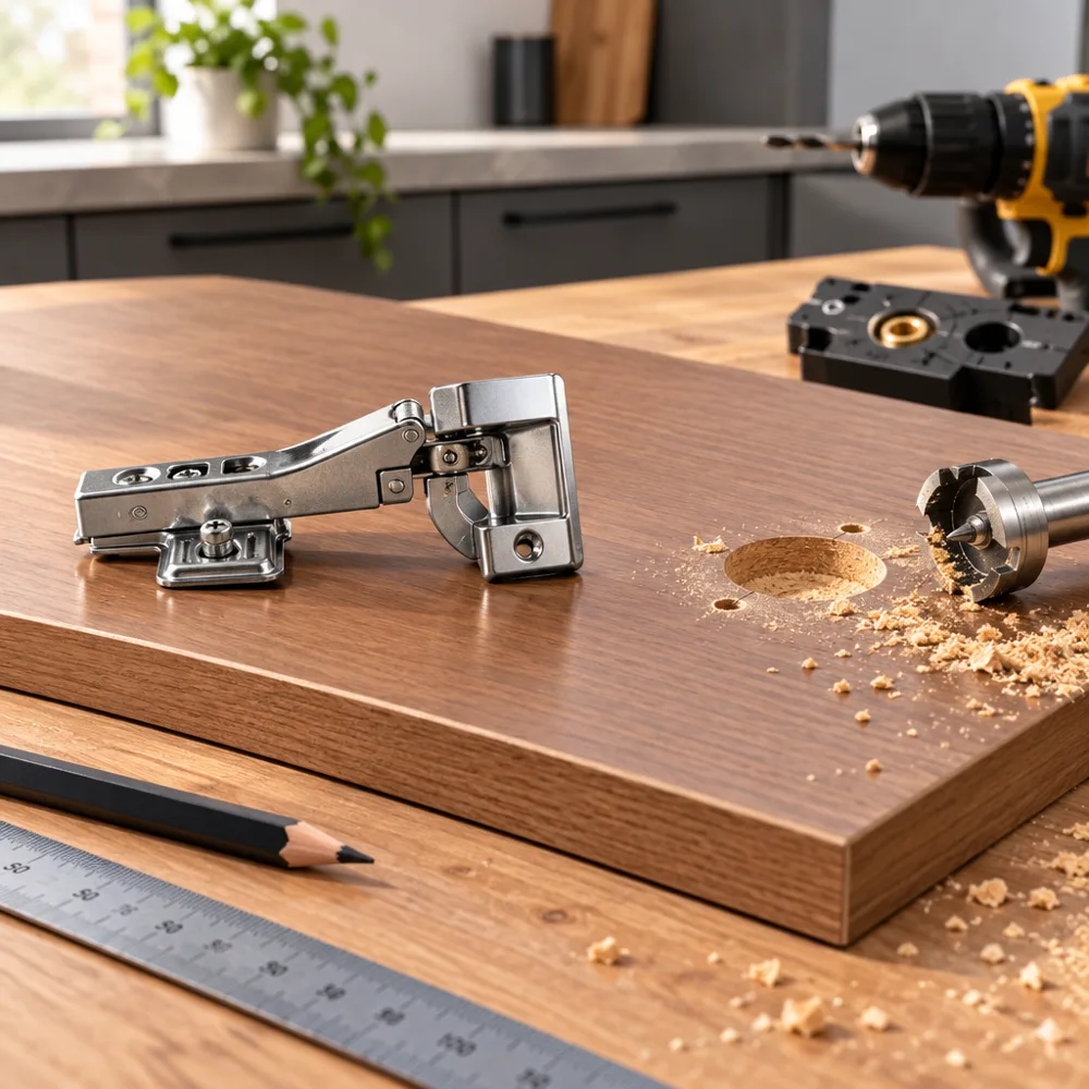
Step 4: Drilling Hinge Flange Pilot Holes
Once you clear the shavings from the 35 mm pocket, set the hinge cup inside the hole to check fit. Place a straightedge or long metal ruler across the back of both hinge bodies to ensure their arms sit perfectly parallel and perpendicular to the door edge.
Using a spring-loaded self-centering Vix bit, drill pilot holes through the hinge flange screw eyelets. Choose the pilot-hole diameter from the hinge manufacturer’s instructions and the screw manufacturer’s guidance, since screw type, length, and core material all affect it. For example, one Blum installation guide specifies a 3 mm pre-drill for its supplied #6 screws.
Step 5: Test-Fitting the Hinge Body
Drive the flange screws into your fresh pilot holes using a handheld manual screwdriver. Power impact drivers deliver uncontrolled rotational torque that easily strips threads in soft particleboard or lightweight fiberboard cores.
Inspect the installed hinge cup from side angles. The perimeter metal flange must seat completely flat against the inside face of the door without tilting, wobbling, or pinching any trapped sawdust underneath the casting.
Installing the Mounting Plate and Hanging the Cabinet Door
Cabinet-Side Layout and System Hole Alignment
On frameless cabinets built to a compatible 37/32 system, the mounting-plate line is commonly positioned 37 mm from the cabinet front edge and uses 32 mm vertical spacing. Other mounting plates use different drilling patterns or screw locations, so confirm the exact plate drawing before drilling.
If you work with face-frame cabinets, specialized compact mounting plates clamp or screw directly onto the inner edge of the solid hardwood frame stiles. Measure the vertical centerline from the cabinet floor or base rail to mirror your door’s top and bottom hinge centers exactly.
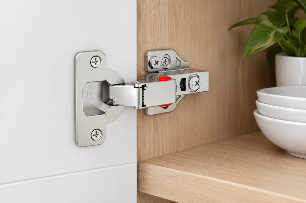
Engaging the Hinge: Slide-on vs. Clip-on Mechanisms
Older hardware requires sliding the hinge arm under a retaining screw on the mounting plate and tightening it down. Many modern hinges use tool-free clip connections that attach without loosening any screws.
For clip-on hinges, engage the arm according to the manufacturer’s installation diagram and verify that the locking feature is fully seated before releasing the door. Slide-on and screw-fixed models require different procedures, so follow the instructions for the specific hinge you bought.
Fine-Tuning and 3D Door Alignment
Vertical, Lateral, and Depth Calibration
One of the main benefits of concealed European hardware is three-dimensional adjustability. 3D adjustment can correct small installation and alignment errors within the hinge’s specified range, but it cannot replace accurate cup-hole placement or compensate for a tilted or excessively deep recess. Typical adjustments work as follows:
- Lateral (Side-to-Side) Adjustment: Turning the front-most eccentric screw shifts the door horizontally across the face of the cabinet, correcting perimeter gaps between twin doors.
- Height (Vertical) Adjustment: Loosening the mounting plate base screws allows the door leaf to shift vertically, aligning top reveals across a continuous run of cabinets.
- Depth (In-and-Out) Adjustment: Turning the rear eccentric cam moves the door leaf toward or away from the cabinet box, preventing the back edge from binding against the carcass face when swinging.
Troubleshooting Post-Installation Alignment Issues
When cabinet doors hang crooked or scrape the face frame, systematic mechanical adjustments usually resolve the problem faster than unfastening hinges or redrilling pockets.
| Visual Symptom | Probable Mechanical Cause | Corrective Action |
|---|---|---|
| Door binds against carcass when opening | Inadequate edge distance or depth set too close | Adjust rear depth cam outward to increase clearance |
| Uneven gap between adjacent double doors | Unequal lateral cam settings | Turn front lateral screws to center the doors evenly |
| Door sags and rubs bottom cabinet rail | Loose mounting plate or vertical shift | Support door weight, loosen plate screws, adjust height |
| Hinge cup loose inside the 35 mm pocket | Flange screw holes stripped out in panel | Use a properly sized hardwood plug, commercial hinge-repair insert, or manufacturer-approved repair; let adhesive cure fully, then redrill the pilot hole |
Work slowly during fine adjustment, turning screws in quarter-turn increments. Testing the swing after each slight turn prevents over-correcting, which can introduce secondary alignment errors on opposing hinges.
Selecting Hardware for High-Traffic and Specialty Applications
Soft-Close Damping and Cycle Testing
High-use spaces like kitchens, utility pantries, and bathroom vanities require hardware capable of withstanding constant daily movement. Soft-close models use a damper to slow the door during the final part of its closing travel, and the damping range varies by model.
According to the supplied KEAX product information for Professional Furniture Cabinet Door Hinges, specific models are tested to exceed 80,000 closing cycles and include a buffer on-off feature that lets users adjust the closing speed. The manufacturer reports 38 years of industry experience, distribution to 43 countries, and more than 100 patents. The product range covers modern kitchen cabinetry, bathroom vanity units, wardrobe systems, solid wood doors, and larger residential and commercial interior projects. Before buying any model, ask for its drilling diagram, load chart, and test documentation so your hole layout matches the hinge you actually install.
Corrosion Resistance in Wet Environments
Humid environments like bathrooms, coastal residential builds, and basement laundry suites degrade basic low-grade steel stampings quickly. Moisture exposure leads to surface pitting, rust formation, and seized pivot rivets.
Selected models use copper- and nickel-plated finishes and are reported to have passed a 48-hour salt-spray test, providing reliable resistance to moisture-induced corrosion in demanding installations.
Frequently Asked Questions
What is the standard hole size for concealed cabinet hinges?
The vast majority of standard European concealed hinges require a 35 mm diameter cup hole. However, smaller specialty hardware designed for thin frames or compact cabinetry may call for a 26 mm cup, so always confirm manufacturer specifications before boring.
How deep should a 35 mm cabinet hinge hole be drilled?
Common concealed-hinge cup depths are around 11 mm to 12 mm, but the exact depth must come from the hinge manufacturer’s drilling diagram. On standard 18 mm cabinet doors, that range leaves roughly 6 mm to 7 mm of solid material beneath the hole, protecting the front decorative veneer from tear-out or cracking.
What is the standard setback distance from the edge of the door?
Many concealed hinges use an edge distance around 3 mm to 7 mm, while some models allow a wider range such as 3 mm to 9 mm. Adding the 17.5 mm radius of a 35 mm bit means your drill center point typically sits 20.5 mm to 26.5 mm from the edge, depending on the hinge model and required door overlay.
Can I drill cabinet hinge holes using a standard hand drill?
Yes, you can drill these holes with a regular handheld power drill if you use a sharp 35 mm Forstner bit paired with a commercial drill guide. Freehand drilling without a guide is risky because any tilt will create an uneven, oval recess.
How do I prevent the Forstner bit spur from poking through the front of the door?
Always use an adjustable mechanical stop collar locked securely onto the drill bit shank, or set the positive depth stop on a drill press quill. Test your depth setting on a piece of scrap wood of identical thickness before touching your finished doors.
What should I do if I drilled the hinge cup hole too deep?
If you have over-drilled without breaking through the front face, use a manufacturer-approved hinge repair plate, commercial repair insert, or properly fitted solid repair disc. Ensure that any repair creates a stable, flush seat for the cup and allows the flange screws to hold securely. Temporary shims are only appropriate if the hinge manufacturer permits them and the cup remains fully supported.
How many hinges are needed for tall wardrobe or solid wood doors?
Hinge quantity depends on door height, width, weight, material, and the selected hinge’s load chart. Use the manufacturer’s recommendation. As a general starting point, two hinges may suit light, compact doors, while taller or heavier doors such as wardrobe and solid wood doors commonly need additional hinges.
Conclusion
Knowing how to make holes for cabinet hinges gives you control over your woodworking projects and turns a nervous first cut into a repeatable routine. Choosing a dedicated 35 mm Forstner bit, locking down your depth stop, and measuring boring distance from the hinge’s own drilling diagram greatly reduce the risk of damaging expensive panel faces. Practice your layout and boring technique on offcut panels before drilling finished workpieces. Accurate cup pockets and properly aligned mounting plates give the hinge the best chance of smooth, reliable operation, while final performance still depends on the selected hinge, door load, substrate, and installation quality.
CONTACT US


GuangDong JinLi XiangXing Precision Metal Manufacturing Co., Ltd.
We are always providing our customers with reliable products and considerate services.
If you would like to keep touch with us directly, please go to contact us
-

Home
-

Tel
-

Email
-

Contact