
How to Measure Cabinet Hinges: A Step-by-Step Sizing Guide
- By:
- Date:2026/11/06
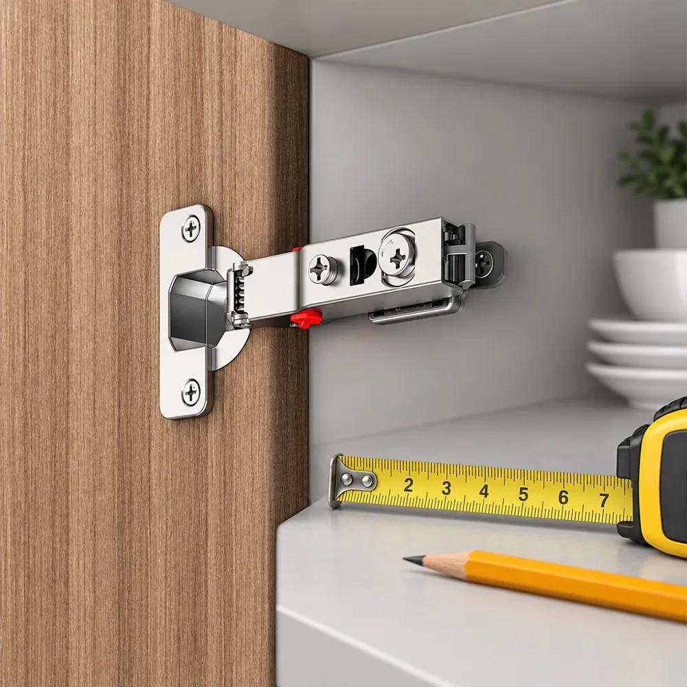
Learning how to measure cabinet hinges accurately is the single most important step before purchasing replacement hardware or upgrading your kitchen casework. A millimeter of discrepancy can cause doors to bind against adjoining casework or leave unsightly, uneven reveals across a bank of doors. When you understand how to measure cabinet hinges and identify their underlying engineering geometry, you eliminate guesswork, protect your cabinet face from redundant screw holes, and guarantee a flush, quiet close.
Cabinet Construction and Hinge Styles
Frameless vs Face-Frame Casework
Cabinet architecture dictates your hardware requirements long before you pick up a ruler. American tradition favors face-frame cabinetry, where a solid hardwood frame surrounds the front perimeter of the plywood box. This frame provides a solid structural anchor, requiring hinges designed to clamp or screw directly onto narrow stiles. European cabinetry, commonly termed frameless or full-access casework, eliminates the face frame entirely. The cabinet door mounts directly to the interior side panel of the carcase.
Hinges engineered for frameless casework require different mounting plate offsets and arm geometry than those built for face frames. Identifying this structural difference immediately narrows your replacement options. The difference between these two construction methods determines whether you will measure against a wood frame perimeter or directly against the interior cabinet side panel.
Concealed European Hinges vs Traditional Exposed Hinges
Concealed cup hinges remain hidden when the door is closed, tucking the pivot mechanism into a circular pocket bored into the back of the door. These systems provide multi-directional adjustability, allowing installers to level uneven doors without redrilling pilot holes. Exposed hinges, such as butt hinges, flush hinges, and wrap-around semi-concealed hinges, display their knuckle and pin along the cabinet exterior.
While exposed hinges depend largely on static alignment and manual shimming, concealed cup hinges operate via a four-bar linkage mechanism. Measuring these two categories requires entirely different reference points. Concealed hinges demand precise cup diameter, depth, and edge-distance measurements, while exposed hinges require leaf dimensions and knuckle barrel positioning.
Replacement Projects vs New Installations
Replacing existing hinges involves matching existing cup mortises and screw centerlines without altering factory woodwork. The goal is hardware interchangeability. You must measure the established bore diameter, hole patterns, and edge distances already machined into the door leaf. The measurements you record during replacement projects must precisely match the physical evidence left by the original hardware to avoid redundant drilling.
New installations offer more flexibility but demand careful planning. You start by calculating desired door reveals, verifying box clearance against appliances, and selecting your preferred boring distance before running a Forstner bit into custom door stock. With new cabinetry, you can optimize hinge placement for the exact door weight, material, and aesthetic preferences without working around pre-existing holes.
Essential Tools and Preparation Checklist
Recommended Measuring Tools
A standard flexible carpenter’s tape measure lacks the rigidity needed for millimeter-precise cabinetry tolerances. Measuring hinge pocket depths or margin gaps with a broad metal hook introduces cumulative errors that throw off door alignment across adjacent cabinets. A digital vernier caliper delivers superior accuracy for measuring cup diameters, bore depths, and tab margins.
If a caliper is unavailable, use a rigid steel machinist’s rule graduated in half-millimeter increments. Keep painter’s tape, a fine-lead mechanical pencil, and a notepad within reach before loosening any fasteners. Recording each measurement immediately prevents confusion when comparing multiple doors or ordering hardware for an entire kitchen run.
Safe Door Removal and Workspace Setup
Never attempt to measure hinge cup pockets while the cabinet door hangs suspended on a single screw. The hanging weight can twist the hinge arm, strip wood fibers around the mounting plate, or fracture the mortise edge. Lay the door face-down on a padded workbench protected by a moving blanket. Support the bottom corner of the door with one hand or a wooden block while releasing the lower hinge mechanism.
If your hardware features quick-release clips, depress the release lever at the tail of each arm. For older slide-on assemblies, back out the rear retaining screw until the arm slides free from the plate. Once the door is flat on the bench, you can measure cup dimensions, screw patterns, and boring distances without risk of damaging the door edge or hinge mortise.
Documenting Hardware Stamps and Markings
Examine the cast metal underbelly of the hinge arm and the backside of the mounting base plate before grabbing measuring tools. Hardware manufacturers frequently stamp technical clues directly into the steel or zinc alloy castings. Look for numbers indicating crank angle, opening radius, or baseplate thickness.
Stamped markings like 0mm, 2mm, or 9mm indicate mounting plate height offsets. Documenting these factory codes alongside your physical measurements simplifies cross-referencing against technical catalog drawings. When you contact a supplier or search an online catalog, these stamped identifiers often correspond directly to model families or hinge series.
How to Measure Cabinet Door Overlay and Inset
Understanding the Geometry of Overlay
Overlay defines the surface area of the cabinet box or face frame covered by the door when closed. It is the distance the door extends past the cabinet side or face-frame edge on the hinge side. Determining overlay is the central calculation for achieving clean gaps between adjoining cabinet panels. To measure overlay on an existing door, close the door completely and apply a short strip of blue painter’s tape to the cabinet frame along the hinge side.
Trace a sharp pencil line along the outer edge of the door directly onto the tape. Open the door and measure from that mark to the edge of the cabinet side or face frame, using the manufacturer’s method for your cabinet style. This measurement represents the actual overlay your current hinge produces, which must be matched or adjusted when selecting replacement hardware.
Full Overlay vs Half Overlay Configurations
Full overlay installations conceal almost the entire front edge of the cabinet carcase, typically leaving a minimal reveal margin between adjacent doors. In frameless casework, full overlay coverage varies by hinge series, boring distance, and mounting plate height, relying on straight-arm or shallow-crank hinge profiles. Half overlay, or dual-door mounting, occurs when two separate cabinet doors share a single vertical partition wall.
When two doors share a partition, each hinge must provide the required partial or twin overlay while preserving the manufacturer’s specified center reveal and clearance. The exact hinge crank, mounting plate height, and door thickness all determine the final center gap. Always consult the manufacturer’s overlay chart rather than assuming that each door simply covers half the partition width.
Inset Doors and Reveal Calculations
Inset cabinetry places the door flush inside the cabinet carcase rather than resting on top of the frame. The perimeter edges of an inset door sit inside the opening, leaving a visible gap known as the reveal. Inset installations require a hinge and mounting-plate combination designed for the cabinet construction and required reveal. Use the manufacturer’s application chart to confirm the required arm geometry and clearances. When measuring inset applications, record the opening’s internal width and height, followed by the exact door dimensions.
Subtract the door dimensions from the opening dimensions to determine total clearance. Choose the reveal from the hinge manufacturer’s installation chart. The required minimum changes with door thickness, edge radius, opening angle, and hinge geometry. Never assume that a standard reveal applies across all hinge models or cabinet constructions.
| Door Application | Cabinet Box Style | Typical Arm Profile | Primary Clearance Concern |
|---|---|---|---|
| Full Overlay | Frameless / Face-Frame | Straight Arm or Shallow Crank | Clearance to adjacent wall or trim |
| Partial Overlay | Traditional Face-Frame | Compact / Shallow Crank | Frame width coverage |
| Half Overlay (Dual) | Shared Partition Wall | Cranked Arm | Hinge screw collision inside shared wall |
| Inset / Flush | Frameless or Beaded Frame | High Crank | Perimeter gap consistency (reveal) |
Measuring Concealed Hinge Cups and Boring Patterns
Measuring Cup Diameter and Pocket Depth
The hinge cup houses the hinge mechanism and, on soft-close models, the damper. Most concealed hinges use a 35 mm cup, while compact systems may use a 26 mm cup. Always verify the manufacturer’s specification for the door thickness and hinge model. Measure the diameter across the circular pocket, avoiding the screw flange extensions. Next, measure the cup depth from the back face of the door down to the flat bottom of the pocket.
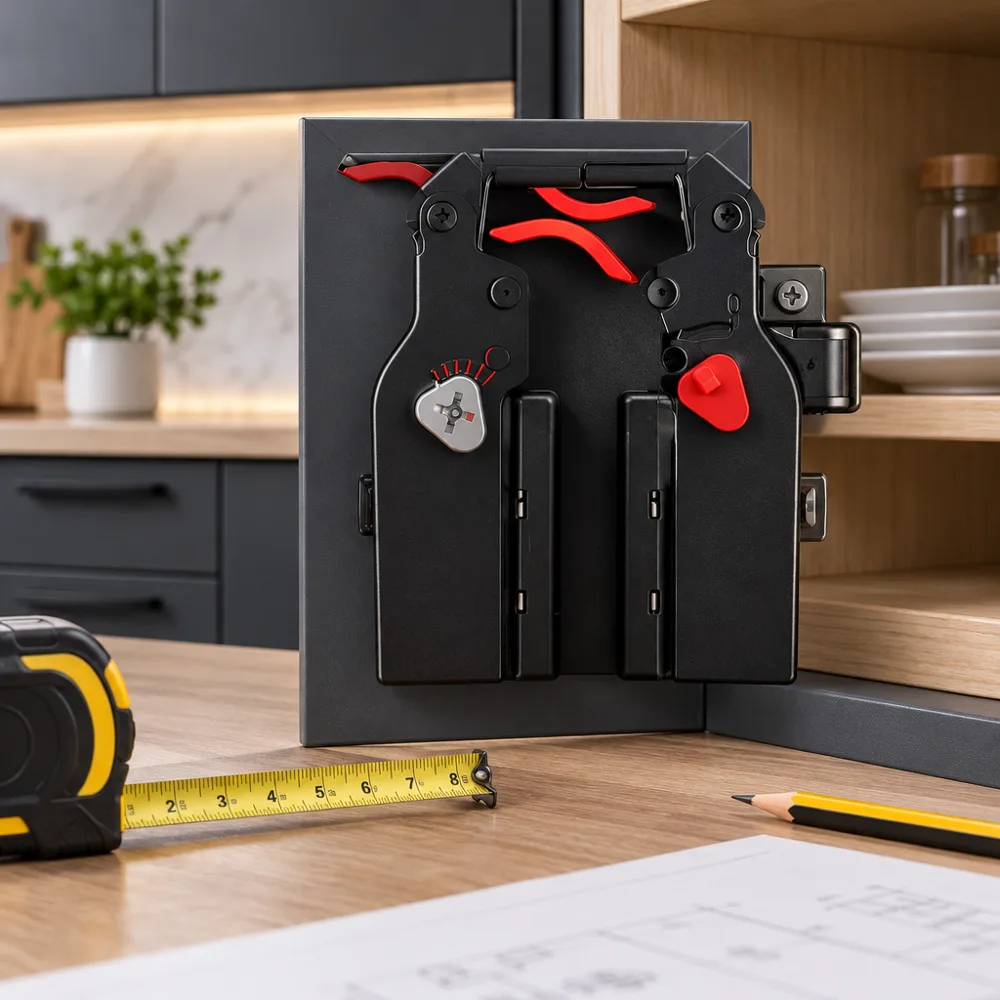
Cup depth is model-specific; examples from current manufacturer specifications range from about 7.8 mm to 12.8 mm. Match the existing bore depth to the replacement hinge’s technical drawing. Drilling shallower prevents the hinge from seating flush, while drilling deeper risks punching through the decorative door face.
Measuring Boring Distance (Tab or K Dimension)
The boring distance is the narrow strip of wood between the outer edge of the door and the nearest edge of the cup bore. This small strip determines the door’s pivot sweep and directly impacts overlay coverage. This dimension is commonly identified as K, TAB, B, or cup distance depending on the manufacturer. Use the exact terminology and reference point shown in the selected hinge’s technical drawing.
- Lay a rigid steel rule across the back of the door, perpendicular to the hinge edge.
- Measure the exact wood shoulder remaining between the door edge and the rim of the cup.
- Note whether the distance falls into common specifications, typically between 3 mm and 7 mm.
- Avoid confusing this tab distance with the distance to the cup center, which equals the tab plus half the cup diameter.
Determining the Screw Hole Pattern
Many screw-on hinge cups are secured by two lateral screws or fixing points, but press-in, dowel, and other mounting systems also exist. Identify the fixing method before measuring the pattern. The spacing between these fixing centers varies by hardware manufacturer, making it critical to identify before buying replacements.
Hole pitch is model-specific. For example, some product ranges use 45 mm, 48 mm, or 52 mm patterns, but the exact pitch and orientation must be matched to the replacement hinge. If the holes are offset from the cup centerline, measure both the horizontal distance between screw centers and the vertical setback from the cup center to ensure a direct drop-in fit.
Measuring Mounting Plates and Cabinet Box Spacing
System 32 Spacing on Cabinet Walls
The mounting plate fastens the hinge arm to the internal cabinet carcase. System 32 commonly uses 32 mm vertical pitch, while the hole-line setback may be 37 mm, 32 mm, or another manufacturer-specific dimension. Measure the existing hole line and match the replacement plate. Measure the vertical distance between the two screw holes on your existing cabinet baseplate.
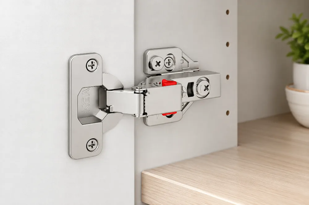
A 32 mm vertical pitch may help identify a compatible system, but direct replacement also requires matching the hole-line setback, fixing pattern, plate type, and screw dimensions. If your casework uses non-standard pilot spacing, verify whether the new plate covers the old screw footprint cleanly. Some mounting systems use single-screw fixing at non-standard centers or rely on cam-lock dowel inserts rather than pilot screws.
Mounting Plate Height Offset
Mounting plates are manufactured in varying heights, often designated as 0 mm, 2 mm, 3 mm, or 9 mm thicknesses. The plate height directly affects the hinge arm’s resting elevation and works in tandem with the cup boring distance to determine final overlay. Plate thickness represents the physical rise of the mounting base off the cabinet panel surface.
Use the selected manufacturer’s formula for overlay calculation. A common form is overlay equals fixed hinge distance plus boring distance minus plate height, but the fixed distance or hinge constant varies by hinge series. Thicker plates lower door overlay, while thinner plates push the door edge further outward over the carcase frame. Always verify the exact formula in the hinge’s technical documentation.
Clip-On Mechanisms vs Slide-On Plates
Examine how the hinge arm engages the mounting plate. Older concealed hinges use a slide-on mechanism where the arm slots over a single securing screw on the plate and tightens into place. Aligning multi-door runs with slide-on hinges can be cumbersome when fine-tuning positions. Modern hardware favors snap-on interfaces, such as one-shaped plane base designs with quick-release latches.
These systems permit tool-free door installation and removal without disrupting mechanical alignment settings. When changing from slide-on to clip-on hardware, use the matching clip-on mounting plate. For a slide-on replacement, retain the existing plate only after confirming compatibility with the new hinge arm. Mixing hinge arms and mounting plates from different manufacturers or incompatible series can prevent proper engagement or disable adjustment functions.
How to Select the Correct Replacement Hinge
Matching Dimensions to Manufacturer Specification Sheets
Once you have compiled your measurements—cup diameter, cup depth, boring distance, overlay, and plate height—cross-reference these figures against engineering catalog charts. Do not rely on generic product labels; compare your field notes against the manufacturer’s dimensional schematics. Verify that your recorded boring distance matches the manufacturer’s recommended range for the desired overlay.
If your door has a 5 mm edge distance and you need a specific overlay, check the manufacturer’s overlay matrix to confirm which plate height achieves that exact combination. The overlay matrix accounts for hinge constant, door thickness, plate height, and boring distance simultaneously. Selecting hardware based on cup diameter alone without consulting the full specification matrix frequently results in misaligned doors.
Factoring Door Thickness and Hinge Count
A 35 mm cup diameter alone does not confirm compatibility. Check the hinge’s permitted door-thickness range, cup depth, edge distance, opening angle, and clearance chart. Select hinge quantity from the manufacturer’s load and installation chart. For tall or heavy doors, follow the specified hinge spacing and load limits rather than relying on a universal count.
Door height, width, weight, material, hinge model, and mounting method all affect the required number of hinges. Solid hardwood doors, glass-insert doors, and wide pantry doors impose different mechanical loads on hinges compared to lightweight melamine overlay doors. Always confirm the hinge’s tested load capacity and the manufacturer’s recommended spacing before finalizing your hardware order.
Durability and Mechanical Refinement
When replacing worn cabinetry hardware, consider upgrading to components engineered for long-term cycling and corrosive domestic environments. Hardware produced by specialized manufacturers incorporates rigorous testing standards. For the supplied KEAX product range, the manufacturer states that specific models are tested for more than 80,000 closing cycles and withstand 48-hour salt spray corrosion resistance tests.
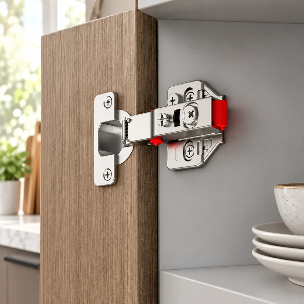
The manufacturer also states that its materials and manufacturing processes comply with Euro E1 requirements. Verify the cycle rating and exact declarations for the model being purchased. The supplied KEAX product data states that specified models use copper and nickel plating and pass a 48-hour salt-spray test. Treat this as a corrosion-resistance specification, not a guarantee against damper or thread problems in every installation environment.
Dry-Fitting, Alignment, and Fine-Tuning
Performing a Single-Hinge Dry Fit
Before drilling or securing an entire set of cabinet doors, perform a clamp-assisted test installation on a single door. Fasten the hinge cups into the pre-bored cavities and snap the hinge arms onto the cabinet mounting plates. Gently swing the door through its full arc to check clearance. Observe the movement closely.
Open the door through its initial movement and full intended arc, checking for rubbing at the heel, side panel, frame, and adjacent door. If binding occurs, consult the hinge clearance chart rather than assuming one cause. Rubbing can result from incorrect overlay, inadequate reveal, side-panel clearance issues, insufficient hinge opening angle, or incorrect plate position. Testing a single door before committing to the entire installation prevents repeating alignment errors across multiple cabinet units.
Adjusting 3D Alignment Screws
Concealed hinges provide multi-directional adjustability via integrated cam screws located on the hinge body or mounting plate. These adjustments allow you to correct minor measurement deviations without moving mounting plates. Depending on the model, separate adjustments control lateral position, depth, and height. Identify each screw from the hinge’s installation instructions instead of assuming the same screw layout across brands.
Lateral adjustment moves the door left or right across the opening face. Depth adjustment moves the door in or out relative to the cabinet face. Height adjustment moves the door up or down on the mounting plate. Lateral adjustment involves turning the appropriate adjustment screw clockwise or counterclockwise to shift the door edge left or right across the cabinet face, evening out vertical gaps between paired doors.
Depth adjustment requires loosening or rotating the eccentric screw to slide the door closer to or further from the cabinet box, preventing rubbing against frame edges. Height adjustment uses the designated cam or screw on the mounting plate to raise or lower the door leaf, ensuring parallel horizontal sightlines across adjacent doors. These three independent axes of adjustment permit fine-tuning without redrilling mounting plates or cup pockets.
Common Measurement Pitfalls to Avoid
Measuring the door width instead of overlay is a frequent error. Measuring the door itself does not indicate how much frame it covers. Always calculate the distance the door laps over the interior box opening. The door width minus the opening width yields total overlay for both hinge and latch sides combined, which must then be divided or apportioned correctly. Assuming universal screw centerlines creates problems during installation.
While 35 mm cup diameters are standard, screw dowel patterns such as 45 mm versus 48 mm versus 52 mm are not interchangeable without plugging holes. Overlooking cup boring distance causes alignment issues. Installing a hinge built for a 3 mm tab into a door drilled at 6 mm shifts the door pivot, reducing overlay and potentially binding the door against the frame. Ignoring side-panel thickness leads to uneven reveals.
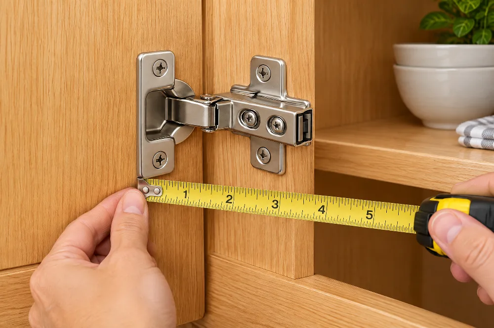
A full overlay hinge configured for a 19 mm side gable will leave an uneven reveal if installed on a 16 mm carcase without adjusting baseplate height. Each of these errors stems from measuring or selecting hardware in isolation rather than cross-referencing all dimensions against the manufacturer’s complete specification chart.
Frequently Asked Questions
What are the most critical measurements needed to replace a cabinet hinge?
You must measure five core dimensions: cabinet door overlay, hinge cup diameter, cup bore depth, edge boring distance (the tab between cup edge and door perimeter), and mounting screw center-to-center spacing on both door and cabinet plate. These five measurements define the hinge geometry and ensure that replacement hardware matches the existing installation footprint.
How do I measure cabinet door overlay if the old hinges are missing?
Measure the width of the cabinet door, then measure the clear internal opening width of the cabinet box. This calculation works only when paired doors and reveals are symmetrical. For that case, subtract the opening width from the door width, then divide the remainder by two. Otherwise, measure each door’s intended overlap against the hinge-side and center-opening edges separately. For single-door openings, position the door flush against the non-hinged reveal side and measure the overlap remaining on the hinge frame.
Is a 35 mm hinge cup universal across all concealed hinge brands?
While the 35 mm diameter bore is an industry-standard dimension, the depth of the cup and the center-to-center spacing of the flanking screw holes vary among manufacturers. A 45 mm hole pattern will not seat into a door drilled for a 48 mm pattern without filling and redrilling screw holes. Always verify cup depth, screw pitch, and fixing method in addition to cup diameter.
What is the boring distance or K dimension on a concealed hinge?
The boring distance is the edge margin between the perimeter of the door and the rim of the drilled cup hole. This dimension is commonly identified as K, TAB, B, or cup distance depending on the manufacturer. It governs the door swing arc and overlay reach. Always use the exact terminology and reference point shown in the selected hinge’s technical drawing to avoid measuring from the wrong reference edge.
How do I know whether my cabinet door is inset or overlay?
Close the cabinet door and examine its surface alignment relative to the surrounding cabinet carcase. If the entire door sits flat on top of the cabinet face and covers the opening edges, it is an overlay door. If the door face sits flush inside the cabinet opening, bordered on all sides by the cabinet frame, it is an inset door. The hinge crank and mounting plate must match the application type.
Can I swap slide-on hinges for modern clip-on soft-close hinges?
Yes, provided the replacement hinge cup fits your door’s existing bore and edge tab distance. However, you must replace the old slide-on mounting plate on the cabinet carcase with the matching clip-on baseplate designed specifically for the new hinge arm. The clip-on interface geometry differs from slide-on systems and requires the manufacturer’s designated mounting plate.
Conclusion
Mastering how to measure cabinet hinges transforms what appears to be a frustrating trial-and-error project into a predictable technical task. Cabinetry alignment depends on mechanical tolerances measured in millimeters rather than broad estimates. By systematically recording your cabinet construction type, door overlay margins, cup bore depths, and plate elevations, you ensure that every replacement hinge seats cleanly into existing woodwork on the first try. Take the time to record exact dimensions with a reliable caliper or steel rule before placing an order. Accurate measurements improve the chance of a clean fit and reliable operation, provided the hinge’s load rating and installation requirements are also met.
CONTACT US


GuangDong JinLi XiangXing Precision Metal Manufacturing Co., Ltd.
We are always providing our customers with reliable products and considerate services.
If you would like to keep touch with us directly, please go to contact us
-

Home
-

Tel
-

Email
-

Contact