
The Engineering Behind Hardware: How to Install Hinges on a Cabinet Door
- By:
- Date:2026/09/20
Understanding precise mechanical forces is essential before learning how to install hinges on a cabinet door. A misaligned cabinet front is rarely just a cosmetic issue. It usually signals a fundamental collapse in load distribution across the hardware framework. Weight transfers through microscopic pivot points.
When gravity pulls a heavy wooden panel downward, the mounting base absorbs immense rotational torque. This mechanical stress concentrates directly on the tiny steel screws anchoring the metal to the wood substrate. If those specific anchors strip, the entire mechanism inevitably fails.
We must look beyond the superficial surface finish of the metal. True hardware reliability stems from mathematical geometry, structural metallurgy, and precise kinematic control. The physical connection between a static frame and a dynamic door demands strict engineering tolerances.
The Physics of Rotational Torque and Load Distribution
A cabinet door acts as a lever arm attached to a structural fulcrum. The wider the door, the greater the downward force exerted on the top hardware assembly. This physical reality dictates every aspect of industrial hinge design. The system must counteract continuous gravitational pull.
When dealing with dense materials like solid oak or thick aluminum frames, the leverage increases significantly. The top hinge experiences extreme pulling forces, constantly attempting to rip the screws from the cabinet wall. The bottom hinge simultaneously absorbs severe crushing forces.
Determining the correct number of anchor points requires calculating the total mass and height of the panel. A standard door measuring under nine hundred millimeters tall typically requires two separate pivot connections. When a door exceeds this vertical span, the material introduces a high risk of warping.
Adding a third connection point in the center stabilizes the wood, preventing it from bowing outward in high humidity. However, this third point of contact complicates the kinematic movement. All three pivot axes must align precisely on the exact same vertical plane.
Preparing the Substrate and Excavating the Cavity
Proper hardware integration always begins with the precise excavation of the circular mounting cavity. A standard Forstner bit creates a flat-bottomed hole, usually thirty-five millimeters in diameter. This specific geometry provides maximum surface area contact between the metal and the wood fibers.
If the cavity is drilled even one millimeter too deep, the remaining wood substrate weakens drastically. This structural deficit reduces the holding power of the primary mounting screws. A shallow cavity prevents the metal from seating flush, altering the entire mathematical geometry of the swing.
The Mechanics of the Flat Mounting Plate
The mounting plate serves as the critical anchor point for the entire dynamic mechanical system. Utilizing a one-shaped plane base design maximizes the contact patch against the cabinet side. This flat architecture distributes rotational stress over a much wider surface area.
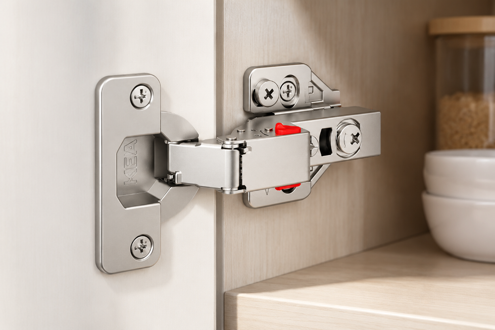
Older hardware designs relied on narrow cross-shaped plates that concentrated stress into a tiny vertical footprint. A wider plane base actively resists the twisting motion generated when a heavy door swings outward. The structural integrity of the cabinet wall dictates the ultimate weight limit.
Understanding the Kinematics of Snap-On Engagement
Modern installation relies on snap-on mechanical systems, completely replacing the tedious sliding engagements of older hardware. An any-click system allows the main arm to lock onto the mounting plate with a simple push. This audible click confirms that the internal spring steel has seated correctly.
The locking bar inside the metal arm snaps directly over a precise lip on the base plate. This mechanical interference fit ensures the door cannot detach under normal operating loads. The release trigger, often a brightly colored component, disengages this secure lock instantly.
Lateral and Depth Calibration Vectors
True three-dimensional adjustment transforms a rigid mechanical connection into a flexible, calibratable system. The lateral X-axis adjustment controls the specific physical gap between two adjoining doors. Turning the primary eccentric screw shifts the metal cup slightly left or right within the housing.
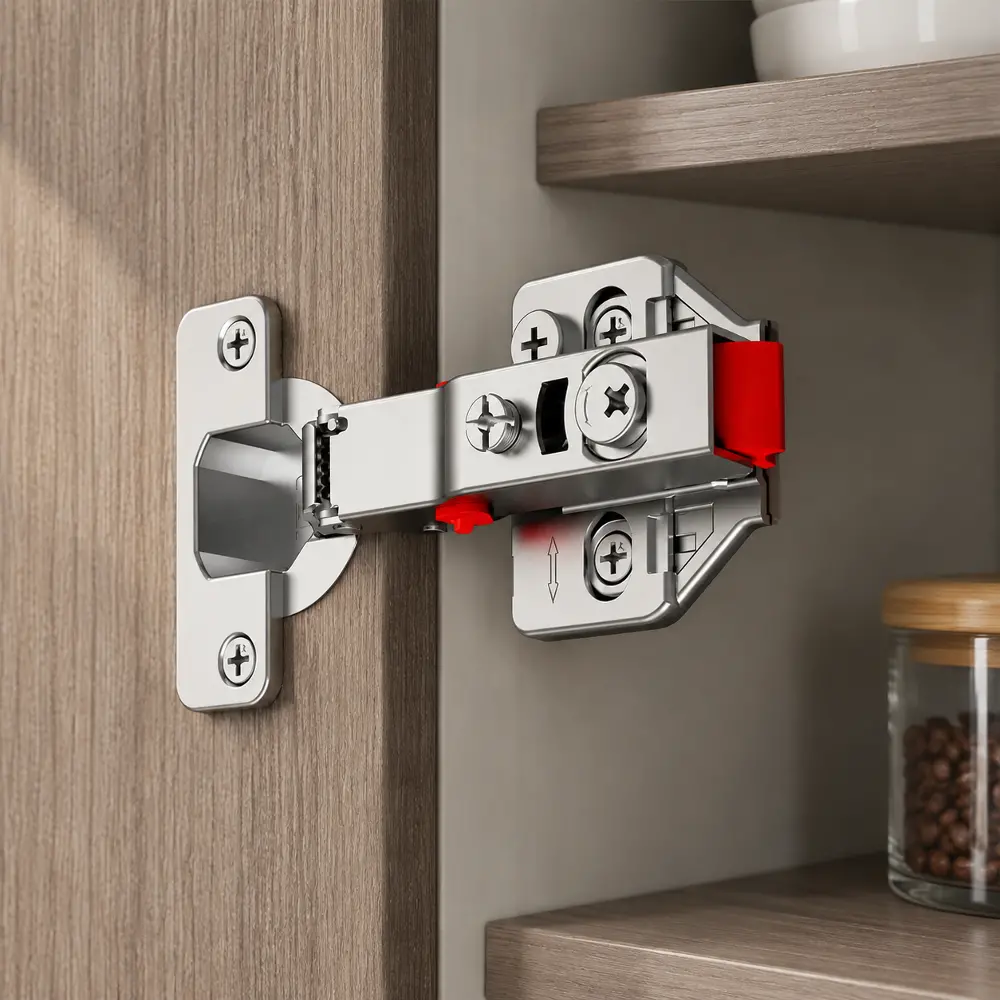
A tiny fraction of a rotation at the pivot translates to a significant movement at the far edge of a wide door. The Z-axis adjustment dictates the spatial depth, controlling the gap between the door back and the cabinet frame. Proper depth calibration prevents the door from binding during rotation.
Vertical Axis Load Management and Adjustments
The Y-axis adjustment specifically manages the vertical positioning of the heavy wooden panel. This mechanism usually involves loosening the primary mounting screws and sliding the entire assembly up or down. Precision cam screws within the plate allow for micro-adjustments without completely removing the structural load.
If a wooden cabinet box settles or shifts over time, the doors will inevitably drop out of perfect alignment. The ability to manipulate the hardware across six distinct directions ensures long-term visual symmetry. Without this capability, maintenance would require plugging and re-drilling the main anchor holes.
Fluid Dynamics Within Hydraulic Damping Cylinders
Soft-closing mechanisms rely entirely on strict fluid dynamics within a miniature hydraulic cylinder. As the door swings shut, a tiny piston pushes through a sealed chamber filled with viscous silicone oil. The oil is forced through a microscopic orifice, generating immense mechanical resistance.
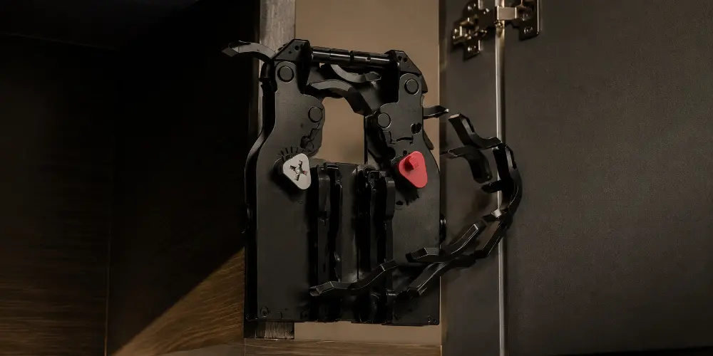
This engineered resistance decelerates the heavy door, converting kinetic energy into a negligible amount of thermal heat. The specific size of the internal bypass valve determines the exact speed of the closure. If the fluid leaks or chemically degrades, the damping effect vanishes immediately.
Regulating User-Controlled Velocity Thresholds
Advanced architectural hardware incorporates buffer on-off technology, allowing precise physical manipulation of the hydraulic resistance. Users can engage or disengage the damping cylinder via a small mechanical switch on the housing. This toggle physically changes the internal pathway of the dense silicone oil.
When installing multiple dampers on a single lightweight door, the double resistance often makes the closing action frustratingly slow. Disengaging the buffer on one single mechanism perfectly balances the kinetic resistance. This level of granular control adapts the hardware to vastly different material weights.
Chemical Substrates and Multi-Layer Electroplating
Bare steel oxidizes rapidly when constantly exposed to atmospheric moisture and oxygen. To combat this physical decay, the raw metal undergoes a rigorous multi-layer electroplating process in a chemical bath. A copper strike layer is applied first, acting as a highly adhesive metallic primer.
Copper bonds deeply with the porous steel substrate, filling microscopic surface imperfections perfectly. A thick protective layer of nickel is then electroplated directly over the copper, providing the final aesthetic finish. This specific chemical combination offers superior environmental resistance against atmospheric degradation.
Environmental Stress and Salt Spray Resistance
Kitchens and bathrooms present harsh working environments filled with steam, organic acids, and variable ambient temperatures. The forty-eight-hour salt spray test is an aggressive simulation of these coastal or high-humidity environments. Hardware is placed inside a sealed chamber and subjected to a continuous saline fog.
This brutal chemical test exposes any microscopic pinholes hidden within the nickel plating layer. If the underlying steel is exposed to the airborne sodium chloride, red rust blooms almost instantly. A passing grade confirms that the copper and nickel layers form a completely impenetrable metallic shield.
Internal Spring Mechanics and Material Deflection
The physical closing force of a cabinet door is governed by a heavy-duty steel spring hidden within the arm. This spring operates under constant mechanical tension, fighting against the hydraulic damper during the final closing phase. The specific metallurgy of this spring is absolutely critical.
Inferior steel alloys suffer from mechanical creep, a physical phenomenon where the metal slowly loses its elasticity. When the spring weakens over time, the door will fail to pull completely tight against the cabinet box. The system relies entirely on high-carbon steel to prevent this fatigue.
Fatigue Testing and Long-Term Mechanical Viability
The true objective measure of structural hardware is its resistance to cyclical mechanical fatigue. Metal physically degrades when bent, stressed, and released up to 80,000 times under load. The pivot pins and spring mechanisms bear the absolute brunt of this continuous physical torture.
For us, understanding these microscopic tolerances has been a strict baseline over thirty-eight years of manufacturing hardware. We have observed that achieving an eighty-thousand cycle threshold requires isolating the hydraulic fluid from microscopic metallic debris during assembly. Production lines must maintain strict mathematical calibration.
Opening a heavy cabinet door ten times a day equates to roughly twenty-one years of continuous usage. The internal spring tension must remain perfectly constant throughout this entire extended lifecycle. Any loss of kinetic elasticity will prevent the door from remaining securely shut against the wooden frame.
Structured Technical Specifications and Tolerances
Evaluating mechanical hardware requires looking at specific, verifiable data points rather than subjective aesthetic opinions. The internal framework must support the intended physical application without straining the underlying materials. The table below outlines the expected baseline metrics for professional-grade architectural hardware systems.
| Metric Category | Baseline Engineering Standard | Real-World Application Impact |
|---|---|---|
| Cycle Endurance | 80,000+ mechanical actuations | Ensures decades of stable operation in high-traffic commercial environments. |
| Corrosion Resistance | 48-hour continuous salt spray | Prevents destructive rust formation in humid coastal or residential bathrooms. |
| Spatial Adjustment | 3D calibration across 6 axes | Allows perfect door alignment despite an irregular or warped cabinet framework. |
| Damping Control | Switchable buffer technology | Accurately matches the final closure speed to the exact door weight. |
| Surface Treatment | Copper-plated under nickel-plated | Eliminates surface flaking and prevents microscopic airborne moisture penetration. |
Frequently Asked Technical Hardware Questions
Understanding the common physical pitfalls of hardware integration prevents catastrophic mechanical failures down the line. We must analyze the specific symptoms of a failing structural system to apply the correct geometric correction. Below are the most frequent technical anomalies encountered during professional installation.
Why do wooden doors bind against the cabinet frame despite accurate initial measurements?
Wood fibers constantly expand and contract based on ambient room humidity and temperature. If the lateral adjustment screws are set to their absolute maximum limit, any material expansion will cause physical interference. Always leave at least one millimeter of mechanical adjustment travel during initial setup.
Does altering the closing speed compromise the internal hydraulic pressure seal?
Disengaging the mechanical buffer simply opens a wider physical bypass channel for the internal silicone oil. It does not pressurize the main cylinder seal or strain the steel piston rod. The fluid dynamics naturally shift to a path of least resistance without causing internal damage.
Why does the metallic snap-on mechanism occasionally fail to engage securely?
The one-shaped plane base must sit perfectly flush against the interior cabinet wall. If a mounting screw is driven at an angle, the screw head protrudes, physically blocking the arm from seating. The locking bar requires completely unobstructed clearance to snap over the retention lip.
Why do doors sometimes bounce back slightly after closing automatically?
This physical anomaly occurs when the internal air pressure within the cabinet box cannot escape quickly enough. The large door acts as a pneumatic piston, compressing the trapped air against the solid back wall. Adjusting the damping cylinder to a slower speed allows the pressure to equalize.
Executing the Final Spatial Calibration
We now return to the core physical methodology of spatial and dimensional calibration. The actual physical installation is only the very first step in creating a functional architectural element. The final mechanical alignment dictates how ambient light reflects off the adjoining doors, requiring extreme patience.
Begin by adjusting the vertical Y-axis to align the top horizontal edges of all doors perfectly flat. Next, manipulate the Z-axis depth to ensure the door rests completely evenly against the rubber cabinet bumpers. The hinges should never pull the panel so tight that the structural frame bends.
Finally, use the lateral X-axis screws to equalize the vertical spatial gaps between adjacent doors. A uniform three-millimeter gap is the strict industry standard for modern full-overlay configurations. Knowing exactly how to install hinges on a cabinet door ultimately means mastering these exact micro-adjustments and understanding the underlying physics.
CONTACT US


GuangDong JinLi XiangXing Precision Metal Manufacturing Co., Ltd.
We are always providing our customers with reliable products and considerate services.
If you would like to keep touch with us directly, please go to contact us
-

Home
-

Tel
-

Email
-

Contact